Whenever someone looks at a model airplane, their eyes are attracted to the cockpit. It seems only natural to expect something interesting inside. Although it may seem daunting to build an instrument panel, when first starting out, keep it simple. You don’t need much of a cockpit interior to make it eye-catching.
GETTING STARTED
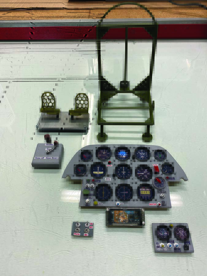
To make an instrument panel, you only need three basic components: First is a backplate of the instrument panel. This will serve as the area where the instrument faces will be placed. Second is an instrument panel face. And third are the instrument bezels.
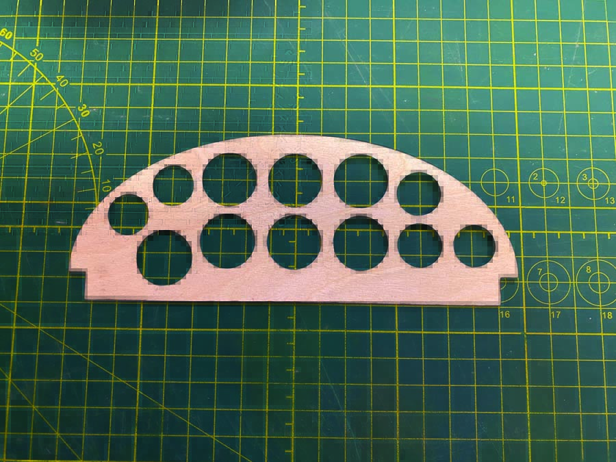
This thin plywood face has cutouts for the instruments.
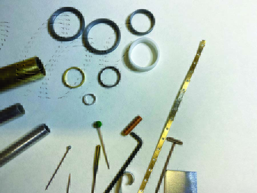
You can make bezels by cutting rigid plastic or aluminum tubes, and pinheads of various sizes can serve as switches. Your scrap box is a treasure-trove!
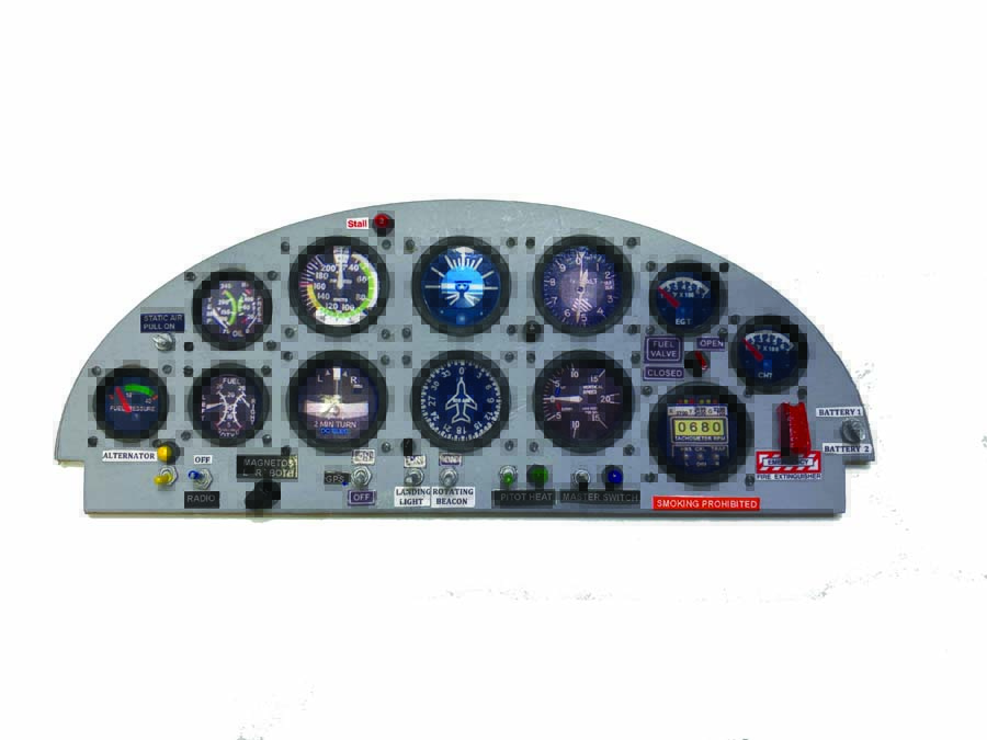
Aircraft like Cessna 172s have basic instrument panels without a lot of bezels.
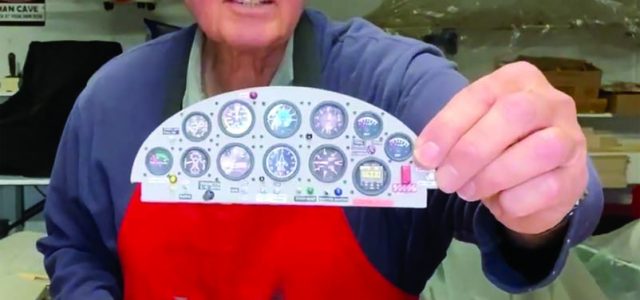
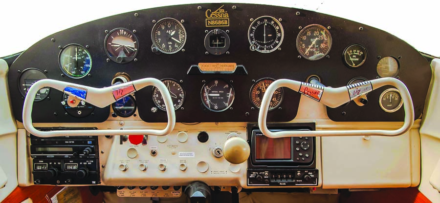
With bezels, switches, simulated lights, and placards, this instrument panel is ready to dress up any ARF!
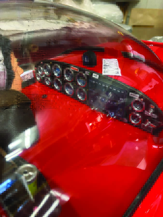
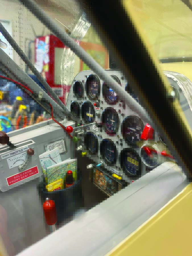
With such a large bubble canopy, the instrument panel of the CAP 10 will immediately catch your attention!
Although bezels have a nice effect, they are not necessarily required in all cases. There are airplanes with instrument panels that do not show any type of bezels and instead have a flush look, such as a Cessna 172 shown here. If you are making an instrument panel for a standoff scale or sport airplane, you can skip adding bezels. However, if you decide to include bezels, you have some options. They can be found in many different sizes from various online sellers. Or if you own a 3D printer or know someone who does, bezels can be printed to your requirements. Another way is to use aluminum tube and a Dremel cutoff saw to make them. If you only need a few, this method works well and the weight gain is negligible. If aluminum tube is not available, try using rigid plastic tube.
As for the instrument faces, there are countless online sources for every kind of instrument. When it comes to standoff scale or sport models, you can choose what fits the look you are after. You can copy the image and resize it on your computer and then it is simply a matter of cutting and pasting. The instrument faces can also be purchased, usually by the same company supplying the bezels. I have even seen instrument faces that were cut out of magazines!
PUTTING THE PANEL TOGETHER
STEP 1
The backplate, which is the same size and shape as the instrument panel, can be made from thin balsa or cardboard.
STEP 2
If you printed your own instrument faces and you are using them in a standoff scale or sport plane, I suggest printing them on glossy photo paper to give the effect of glass over the instrument face. It is surprisingly effective. However, if you are looking for more of a scale look, you can place very thin self-adhesive plastic film between the back plate and the panel face.
STEP 3
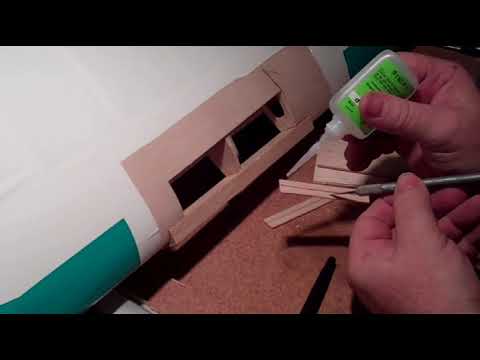
The instrument panel will have to be cut out for the instrument faces. This will also serve as your template to mark the placement of the instruments on the back plate. The instrument panel face can be made from 1/64-inch-thick birch plywood, which has a very fine grain and is easy to finish to obtain a smooth metal look. Due to how thin it is, it is very easy to cut out the instrument cutouts.
Balsa wood can be used and works well but requires more finishing due to its grain. There are various ways to make the instrument cutouts on the panel. You could use a laser cutter if available. Another method I have used is a brass tube, which comes in many different diameters. Sharpen one end with a file, and use it as a drill or a punch. Drill bits also work, but it can be a challenge to achieve a very clean cut with that method.
STEP 4
Now take your instrument panel plate with the cutouts and, using it as a template, draw the position for the instrument faces on the backplate. Then glue your instrument faces to the backplate with a glue stick or Zap canopy glue. Use a glue that will allow you to move the instrument face to its exact position. Do not use CA! As a side note, the placement of flight instruments generally has a pattern often referred to as a “six pack.”
Now place the instrument panel face on top of the backplate with the instrument faces while making any adjustments to the instrument faces, ensuring everything is aligned. When you are pleased with the look of your panel position and instrument faces, glue on the panel. I use a 5-minute epoxy so I have time to line up the panel exactly the way I want it.
If you like, apply miniature screws to the panel to give a realistic look, as that is how real instruments are attached in airplanes. I’ve bought miniature screws from a model railroad shop and various vendors that sell cockpit components. To install the screws, simply drill the appropriate size holes and push the screws into the holes (don’t screw them in). I use a small hand drill to make the holes and drill right through the backplate. Don’t try to glue the screws when placing them in the holes. When all the screws are in place, turn the panel over to the back side and you will see the holes you drilled for them. You can now use medium CA glue and put a small drop on every screw hole. If you try to glue the screws from the front panel side, you risk getting glue on the panel. I speak from experience!
When you have determined what you want your panel to look like to suit the aircraft you are building, it is time to install switches and lights. If you have access to a 3D printer, you could print the necessary components, or you can purchase them from various vendors. You may also be able to find some of these components right in your shop by looking for small items that resemble something you may see on an instrument panel. For example, in my World War 1 airplane, I made some components from small pieces of scraps that I never throw out, such as brass tube, etc.
To finish detailing the panel, you’ll need to apply the appropriate labels and placards. Using a word processor on your computer, you can make various size labels. Then use glossy or satin finish photo paper to print the labels. When applying the switches, lights or labels, I use a toothpick to precisely control the application of glue and use as little glue as possible.
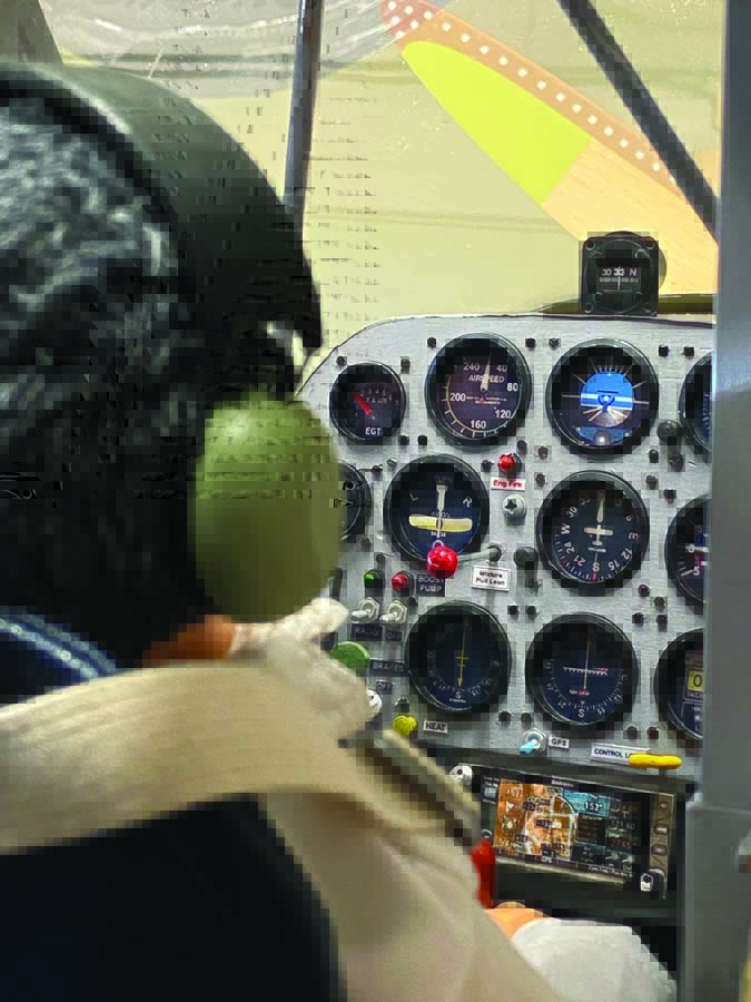
You can now install your completed panel in the airplane and admire the transformation of the model. Don’t forget the pilot! The airplane looks strange being flown by a ghost! For more tips and techniques on creating and installing instrument panels, see my video at ModelAirplaneNews.com/panel.
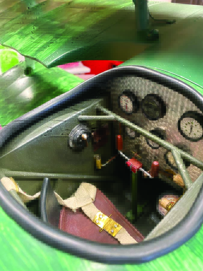
Standoff scale Fokker Dr1 cockpit added.
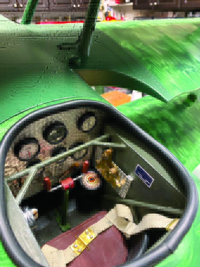
Several parts are bits and pieces of scrap material transformed into cockpit components.
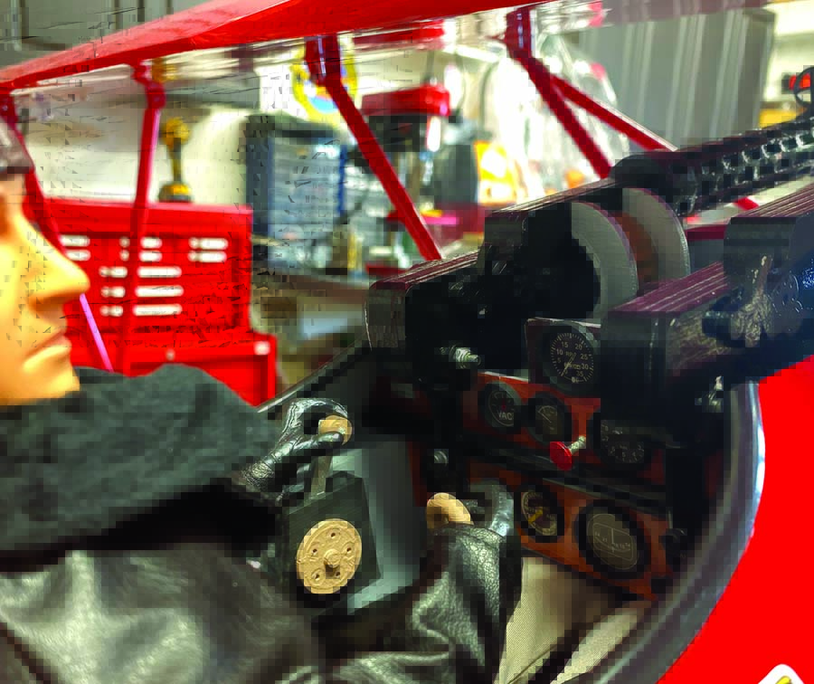
Hangar 9 Fokker D-Vll cockpit transformed from a decal instrument panel and shoulder pilot to something a little more realistic with added bezels, components, and a full-body pilot from Warbird Pilots.
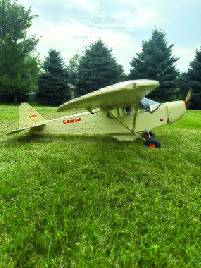
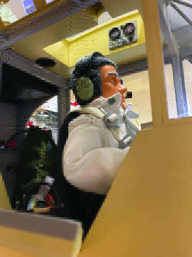
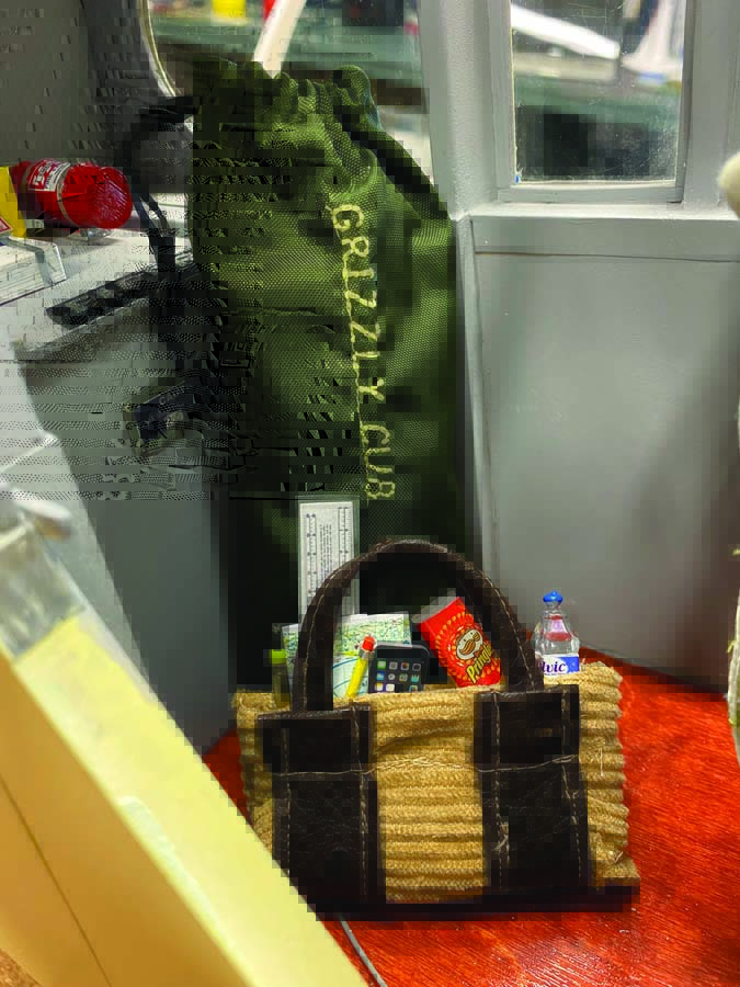
Inside the Grizzly Cub
This 1/4-scale Cub has been modified to resemble a customized Super Cub. I built it using Sig Cub plans. The model is covered with Koverall fabric, has a lighting system and is powered by a DLE 35 engine with an electric start. This cockpit has no signs of any radio equipment, it is all hidden. I even installed a headliner to hide the servo and lighting wires to the wing. I also scratch-built the pilot out of 3D-printed parts and a sewn-up body.
ABOUT THE AUTHOR
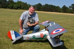
Rick Hanus developed a keen interest in aircraft modelling at the early age of 11, transitioning from U-control to RC aircraft. His passion for airplanes inspired him to pursue a career in aviation, where he held various positions within the industry. He retired as an airline pilot after serving in numerous capacities, including instructor and fleet Chief Pilot for a major airline.
Text & Photos By Rick Hanus