

When building a giant-scale airplane, you don’t want any guesswork with your linkages. The all-important connections between our servo and the control surfaces are absolutely tied to the length of our aircraft’s lifespan. There are several common linkage methods. You can use a solid pushrod of a rather short length for a direct control setup and, for longer distances, you can use a rigid carbon tube or insert a flexible pushrod into a guide sleeve braced securely within the fuselage for precise control. Another popular setup is to use a pull-pull system, which is very common for rudders on giant-scale aerobatic models whenever the rudder servo is located close to the cockpit area. Whichever method you prefer, the installation of these systems must be done properly to ensure the best results.
SERVO BASICS
For your control system to work properly, you have to use the correct servo for a given job. Many aircraft manufacturers offer servo size and type suggestions, and it is always a good idea to use their recommendations. Servos with 200 oz.-in. of torque (or more) are ideal for giant-scale aircraft use—especially when it comes to 3D aerobatic designs. Multiple servos are sometimes used to move a single specific control surface. Keep in mind, though, that the amount of torque really depends on the type of airplane you’re flying. While the 200 oz.-in. example works well for most scale applications up to about a 130-inch wingspan, it will not be enough for a similarly sized aerobatic model where you just can’t have enough servo torque.
Often, to achieve large control surface deflections, you can install a longer servo arm on the servo. However, be sure to also maximize the adjustable travel volume function in your radio. While having low adjustable travel volume and long servo arms can produce large control throws, it will also cause poor mechanical advantage, resulting in flutter and possibly control surface blow-back during flight. Blow-back occurs when the control surface cannot deflect the same amount in the air as it does on the ground, and both flutter and extreme cases of blow-back can be fatal to your plane. Also, it is best to avoid multiple bellcranks and to keep the control linkage system as simple as possible.
MECHANICAL ADVANTAGE
The mechanical advantage that the servo can exert on a control surface is important. As a rule, while maximizing the adjustable travel volume values, the distance from the servo arm’s center screw to the attachment point of the linkage on the arm should be the same as the distance from the hinge centerline (pivot point) to the linkage attachment point on the control horn. For example, if you’re using a 1.5-inch servo arm and the linkage is attached to the servo arm approximately 1.5 inches from the servo screw, then the linkage attached to the control horn should be the same distance (when measured from the hinge line). This principle applies to both “push-pull” and “pull-pull” systems. Using a shorter control horn to increase control surface deflection greatly reduces the servo’s leverage and can result in flutter.
The higher the adjustable travel volume percentage, the higher the servo resolution will be. Decreasing adjustable travel volume percentage will lower servo resolution, which is highly undesirable.
PUSH-PULL CONTROL
A “push-pull” control system simply means that a servo is connected to a single control horn on the control surface. With giant-scale aircraft, the pushrod must be rigid. Most giant aerobatic models feature externally mounted servos that are connected to the control surface with fairly short titanium rods. For short linkages (up to five inches in length), Hangar 9 offers Titanium Pro-Links that have 4-40 threads to accept either a ball-link or swivel-link at each end. For servos mounted a greater distance away from the control surface, pushrod supports are a must!
Where a pushrod runs the length of the fuselage, you can use a fiberglass arrow shaft or a carbon-fiber tube. The pushrod does flex a little while under flight loads, so supports must be located at a few points along the pushrod’s length. Precisely located holes in a few formers can also serve as guides to minimize the amount of side flex, which can cause linkage binding.
PULL-PULL DEFINED
It is quite common to use a pull-pull cable system in aircraft that are prone to tail-heaviness. This method is a lot lighter compared to a pushrod setup of the same length. Cable guides are not often needed and may only be needed if the cable interferes with the airframe structure. Pull-pull systems are closed-circuit setups. There are two attachment points at the servo and at the control surface. The cables always remain the same length, so relative to their pivot points, the geometry of the control horns and the servo arm must remain the same. If they are not, when the servo moves, the cables will slacken and/or tighten as they transmit the motion to the control surface.
If the control horn on the control surface is not aligned properly with the hinge pivot point, an offset servo arm will be needed. The amount of offset in the arm, when measured from the servo arm screw to the attachment points on the arm, must be equal to the offset distance at the control horns.
Nylon-coated, braided steel cable is the best choice for pull-pull systems, and it’s available from RC companies like Du-Bro. You can also find braided cable at most fishing supply outlets that specialize in deep-sea fishing. Called “steel leader cable,” it is nylon-coated and available in several thicknesses—0.032-inch (1/32 inch) works great for giant-scale airplanes.
To attach the cable, a full servo arm or a bell-crank can be used. A ball-link clevis is attached to both ends of the servo arm, or bell-crank, where a threaded rod that has a hole drilled in it to accept the cable connection will be threaded into the ball-link. Using a ball-link and a threaded rod is a must so the tension of the cables are adjustable. Over time, the cables may stretch to some degree. If this occurs, you must tighten the cables so that they are taut for precise control.
To connect the cable at each end, slip a ferrule onto the cable and pull the cable through the hole, letting at least eight inches extend past the hole. Using your fingers, bend the cable into a slight V where it passes the hole and slip the end of the cable through the ferrule. Push the ferrule about a 1/4-inch from the threaded rod and hole that the cable is passed into, and loop the cable around the ferrule once more. When satisfied, crimp the ferrule in between two to three spots, and cut off the excess wire. Repeat this process for the control-horn end of the installation.
CABLE AND PUSHROD ATTACHMENT
Don’t use Z-bends on the ends of your pushrod wires to attach them to your servo arms. Instead, use either a 4-40-size brass clevis or a ball-link clevis. Heavy-duty hardware ensures proper control linkages that will withstand the flight loads exerted on a giant airplane. Sullivan Products and Du-Bro Products make metal clevises that can either thread onto a pushrod wire end with a jam nut or can be soldered into place.
It is best to have a soldered clevis on one end of a pushrod and a threaded clevis on the other. If you use two threaded clevises, vibration can cause the pushrod to unscrew itself from the clevises during flight and that’s never a good thing.
Heavy-duty ball links are also an excellent way to make the connections. Ball-links ensure slop-free movement between pushrods and the servo arms, and are ideal for where there is a slight misalignment in the overall geometry of the linkage. Again, the proper size for giant scale is 4-40.
Biplane Linkages
Giant-scale biplanes pose an interesting problem because if a separate servo isn’t used for each aileron, you must link the upper and lower ailerons to one another with a linkage. Doing so properly will result in the same deflection on all ailerons. However, if this is not done correctly, all ailerons may have different deflection amounts. If you install a linkage between the upper and lower aileron, you must connect the pushrod at the same vertical position on both top and bottom ailerons. That is, if the connector pin is above the trailing edge on the bottom aileron, then the connector pin needs to be equally above the trailing edge on the top aileron. If this rule is not followed, differential between ailerons will exist. Du-Bro Products also offers a large variety of pushrod sizes—up to 30 inches in length. These pushrods move back and forth within plastic or carbon guide tubes, which also must be supported within the fuselage. There are several ways to connect the 4-40 threaded wire ends to the pushrod so the pushrod can connect to the servo arm and control horn. You can do it with commercial pushrod adaptors or by threading the threaded wire into a wood plug and gluing into the ends of the pushrod tube.
FINAL THOUGHTS
Although many control methods are available, it is best to read the instruction manuals provided with your aircraft and use the manufacturer’s recommendations while setting up your model. If you’re unfamiliar with the linkage method, consult an experienced modeler who has built and flown giant airplanes with success. A quick tech conversation could save your airframe!

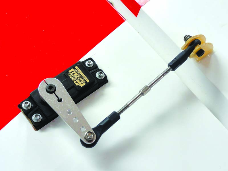
Shown here is an offset arm that is connected via a pull-pull system to the rudder control horn, which is also offset from the hinge line.
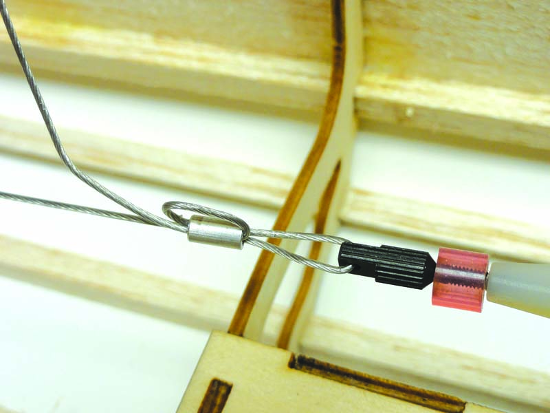
Looping the pull-pull cable through the ferrule ensures that the cable will not pull loose after it’s crimped in place.
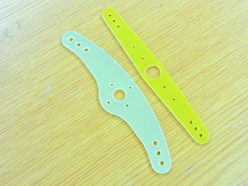
An offset arm as well as a straight arm for pull-pull. Using a straight arm is beneficial whenever the control horn on the control surface is directly in line with the hinge-line. Both arms shown above are to be bolted to a standard plastic or metal servo arm before being secured to the servo.
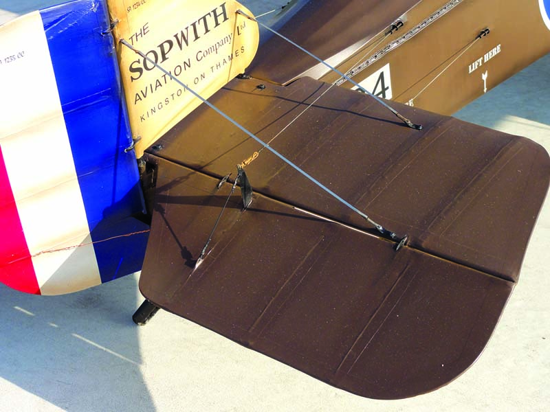
Pull-pull is common among WW I and other vintage aircraft. Shown here is a pull-pull system to control the elevator of this gorgeous Sopwith Pup.
This Hangar 9 Titanium Pro-Link can extend to a maximum length of five inches and is rather convenient whenever a servo is mounted close to the control surface.
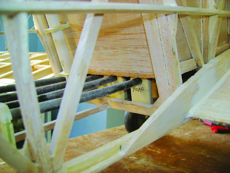
Supports are needed for pushrods that run almost the entire length of the fuselage. (Photo by Raymond Schmidt)
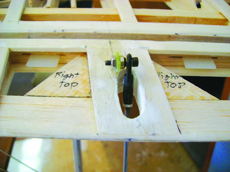
The upper aileron of a giant-scale biplane needs to be properly linked to the lower aileron.
By John Glezellis


Great informative article assembly manuals usually don’t go into that much detail.